Showing posts with label Wireless. Show all posts

Thursday, September 20, 2012

Using WiFi to See Through Walls


In the 1930s, U.S. Navy researchers stumbled upon the concept of radar when they noticed that a plane flying past a radio tower reflected radio waves. Scientists have now applied that same principle to make the first device that tracks existing Wi-Fi signals to spy on people through walls.
Wi-Fi radio signals are found in 61 percent of homes in the U.S. and 25 percent worldwide, so Karl Woodbridge and Kevin Chetty, researchers at University College London, designed their detector to use these ubiquitous signals. When a radio wave reflects off a moving object, its frequency changes—a phenomenon called the Doppler effect. Their radar prototype identifies frequency changes to detect moving objects. It’s about the size of a suitcase and contains a radio receiver composed of two antennas ­and a signal-processing unit. In tests, they have used it to determine a person’s location, speed and direction—even through a one-foot-thick brick wall. Because the device itself doesn’t emit any radio waves, it can’t be detected.
Wi-Fi radar could have domestic applications ranging from spotting intruders to unobtrusively monitoring children or the elderly. It could also have military uses: The U.K. Ministry of Defence has funded a study to determine whether it could be used to scan buildings during urban warfare. With improvements, Woodbridge says, the device could become sensitive enough to pick up on subtle motions the ribcage makes during breathing, which would allow the radar to detect people who are standing or sitting still.
See image above for how it'll work.
1. MOVING SUBJECT
When Wi-Fi radio waves bounce off a moving object, their frequency changes. If, for example, a person is moving toward the Wi-Fi source, the reflected waves’ frequency increases. If a person is moving away from the source, the frequency decreases.
2. REGULAR OL' ROUTER
A Wi-Fi Internet router already in the room fills the area with radio waves of a specific frequency, usually 2.4 or 5 gigahertz.
3. BASELINE SIGNAL
One antenna of the radar system tracks the baseline radio signal in the room.
4. SHIFTED SIGNAL
A second antenna detects radio waves that have reflected off of moving objects, which changes their frequency.
5. PERP, SPOTTED
By comparing the two antennas’ signals, the computer calculates the object’s location to within a few feet as well as its speed and direction.

BREATHE EASY

It’s possible to detect a person’s breathing rate by surrounding him with radio waves. Neal Patwari’s wireless engineering group at the University of Utah designed a network of 20 inexpensive radio transmitters that are placed around a patient’s bed. Then they created an algorithm that detects a stationary person’s breaths better than current detectors do. Patwari plans to upgrade the algorithm by the end of the year to filter out body movements too. The system could someday be used in hospitals in place of tubes and masks.

Thursday, December 1, 2011

LTE / 3GPP

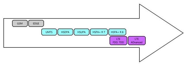
LTE stands for Long Term Evolution. The LTE project was initiated in November 2004 and the focus was on enhancing the Universal Terrestrial Radio Access (UTRA) and optimizing the 3GPP’s radio access architecture.

Evolution

The most important objective of LTE is to achieve the following:

  • Higher Bitrates (100 Mbps DL an 50 Mbps UL)
  • Reduced delays in terms of connection establishment and transmission latency.
  • Increase cell edge bit rate.
  • Network optimization for packet data
  • Simplified NW structure
  • Lower cost per bit
  • Frequency flexibility
  • Seamless mobility between different radio access technologies
  • Reasonable power consumption for UEs

Detailed Requirements

Peak data rate

  • Instantaneous downlink peak data rate of 100 Mb/s within a 20 MHz downlink spectrum allocation (5 bps/Hz)
  • Instantaneous uplink peak data rate of 50 Mb/s (2.5 bps/Hz) within a 20MHz uplink spectrum allocation)

Control-plane latency

  • Transition time of less than 100 ms from a camped state, such as Release 6 Idle Mode, to an active state such as Release 6 CELL_DCH
  • Transition time of less than 50 ms between a dormant state such as Release 6 CELL_PCH and an active state such as Release 6 CELL_DCH

Control-plane capacity

  • At least 200 users per cell should be supported in the active state for spectrum allocations up to 5 MHz

User-plane latency

  • Less than 5 ms in unload condition (ie single user with single data stream) for small IP packet

User throughput

  • Downlink: average user throughput per MHz, 3 to 4 times Release 6 HSDPA
  • Uplink: average user throughput per MHz, 2 to 3 times Release 6 Enhanced Uplink

Spectrum efficiency

  • Downlink: In a loaded network, target for spectrum efficiency (bits/sec/Hz/site), 3 to 4 times Release 6 HSDPA )
  • Uplink: In a loaded network, target for spectrum efficiency (bits/sec/Hz/site), 2 to 3 times Release 6 Enhanced Uplink

Mobility

  • E-UTRAN should be optimized for low mobile speed from 0 to 15 km/h Higher mobile speed between 15 and 120 km/h should be supported with high performance
  • Mobility across the cellular network shall be maintained at speeds from 120 km/h to 350 km/h (or even up to 500 km/h depending on the frequency band)

Coverage

  • Throughput, spectrum efficiency and mobility targets above should be met for 5 km cells, and with a slight degradation for 30 km cells. Cells range up to 100 km should not be precluded.

Further Enhanced Multimedia Broadcast Multicast Service (MBMS)

  • While reducing terminal complexity: same modulation, coding, multiple access approaches and UE bandwidth than for unicast operation.
  • Provision of simultaneous dedicated voice and MBMS services to the user.
  • Available for paired and unpaired spectrum arrangements.

Spectrum flexibility

  • E-UTRA shall operate in spectrum allocations of different sizes, including 1.25 MHz, 1.6 MHz, 2.5 MHz, 5 MHz, 10 MHz, 15 MHz and 20 MHz in both the uplink and downlink. Operation in paired and unpaired spectrum shall be supported
  • The system shall be able to support content delivery over an aggregation of resources including Radio Band Resources (as well as power, adaptive scheduling, etc) in the same and different bands, in both uplink and downlink and in both adjacent and non-adjacent channel arrangements. A “Radio Band Resource” is defined as all spectrum available to an operator

Co-existence and Inter-working with 3GPP Radio Access Technology (RAT)

  • Co-existence in the same geographical area and co-location with GERAN/UTRAN on adjacent channels.
  • E-UTRAN terminals supporting also UTRAN and/or GERAN operation should be able to support measurement of, and handover from and to, both 3GPP UTRAN and 3GPP GERAN.
  • The interruption time during a handover of real-time services between E-UTRAN and UTRAN (or GERAN) should be less than 300 msec.

Architecture and migration

  • Single E-UTRAN architecture
  • The E-UTRAN architecture shall be packet based, although provision should be made to support systems supporting real-time and conversational class traffic
  • E-UTRAN architecture shall minimize the presence of “single points of failure”
  • E-UTRAN architecture shall support an end-to-end QoS
  • Backhaul communication protocols should be optimised

Radio Resource Management requirements

  • Enhanced support for end to end QoS
  • Efficient support for transmission of higher layers
  • Support of load sharing and policy management across different Radio Access Technologies

Complexity

  • Minimize the number of options
  • No redundant mandatory features

Standardization

In 2007, E-EUTRA progressed from feasibility study stage to first approved Technical specification. Theres also LTE Specifications below :

TS 36.101 Evolved Universal Terrestrial Radio Access (E-UTRA); User Equipment (UE) radio transmission and reception .
TS 36.104 Evolved Universal Terrestrial Radio Access (E-UTRA); Base Station (BS) radio transmission and reception .
TS 36.106 Evolved Universal Terrestrial Radio Access (E-UTRA); FDD repeater radio transmission and reception .
TS 36.111 Location Measurement Unit (LMU) performance specification .
TS 36.113 Evolved Universal Terrestrial Radio Access (E-UTRA); Base Station (BS) and repeater ElectroMagnetic Compatibility (EMC) .
TS 36.116 Evolved Universal Terrestrial Radio Access (E-UTRA); Relay radio transmission and reception .
TS 36.117 Evolved Universal Terrestrial Radio Access (E-UTRA); Relay conformance testing .
TS 36.124 Evolved Universal Terrestrial Radio Access (E-UTRA); Electromagnetic compatibility (EMC) requirements for mobile terminals and ancillary equipment .
TS 36.133 Evolved Universal Terrestrial Radio Access (E-UTRA); Requirements for support of radio resource management .
TS 36.141 Evolved Universal Terrestrial Radio Access (E-UTRA); Base Station (BS) conformance testing .
TS 36.143 Evolved Universal Terrestrial Radio Access (E-UTRA); FDD repeater conformance testing .
TS 36.171 Evolved Universal Terrestrial Radio Access (E-UTRA); Requirements for Support of Assisted Global Navigation Satellite System (A-GNSS) .
TS 36.201 Evolved Universal Terrestrial Radio Access (E-UTRA); LTE physical layer; General description .
TS 36.211 Evolved Universal Terrestrial Radio Access (E-UTRA); Physical channels and modulation .
TS 36.212 Evolved Universal Terrestrial Radio Access (E-UTRA); Multiplexing and channel coding .
TS 36.213 Evolved Universal Terrestrial Radio Access (E-UTRA); Physical layer procedures .
TS 36.214 Evolved Universal Terrestrial Radio Access (E-UTRA); Physical layer; Measurements .
TS 36.216 Evolved Universal Terrestrial Radio Access (E-UTRA); Physical layer for relaying operation .
TS 36.300 Evolved Universal Terrestrial Radio Access (E-UTRA) and Evolved Universal Terrestrial Radio Access Network (E-UTRAN); Overall description; Stage 2 .
TS 36.302 Evolved Universal Terrestrial Radio Access (E-UTRA); Services provided by the physical layer .
TS 36.304 Evolved Universal Terrestrial Radio Access (E-UTRA); User Equipment (UE) procedures in idle mode .
TS 36.305 Evolved Universal Terrestrial Radio Access Network (E-UTRAN); Stage 2 functional specification of User Equipment (UE) positioning in E-UTRAN .
TS 36.306 Evolved Universal Terrestrial Radio Access (E-UTRA); User Equipment (UE) radio access capabilities .
TS 36.307 Evolved Universal Terrestrial Radio Access (E-UTRA); Requirements on User Equipments (UEs) supporting a release-independent frequency band .
TS 36.314 Evolved Universal Terrestrial Radio Access (E-UTRA); Layer 2 - Measurements .
TS 36.321 Evolved Universal Terrestrial Radio Access (E-UTRA); Medium Access Control (MAC) protocol specification .
TS 36.322 Evolved Universal Terrestrial Radio Access (E-UTRA); Radio Link Control (RLC) protocol specification .
TS 36.323 Evolved Universal Terrestrial Radio Access (E-UTRA); Packet Data Convergence Protocol (PDCP) specification .
TS 36.331 Evolved Universal Terrestrial Radio Access (E-UTRA); Radio Resource Control (RRC); Protocol specification .
TS 36.355 Evolved Universal Terrestrial Radio Access (E-UTRA); LTE Positioning Protocol (LPP) .
TS 36.401 Evolved Universal Terrestrial Radio Access Network (E-UTRAN); Architecture description .
TS 36.410 Evolved Universal Terrestrial Radio Access Network (E-UTRAN); S1 general aspects and principles .
TS 36.411 Evolved Universal Terrestrial Radio Access Network (E-UTRAN); S1 layer 1 .
TS 36.412 Evolved Universal Terrestrial Radio Access Network (E-UTRAN); S1 signalling transport .
TS 36.413 Evolved Universal Terrestrial Radio Access Network (E-UTRAN); S1 Application Protocol (S1AP) .
TS 36.414 Evolved Universal Terrestrial Radio Access Network (E-UTRAN); S1 data transport .
TS 36.416 Mobile Relay for E-UTRA .
TS 36.420 Evolved Universal Terrestrial Radio Access Network (E-UTRAN); X2 general aspects and principles .
TS 36.421 Evolved Universal Terrestrial Radio Access Network (E-UTRAN); X2 layer 1 .
TS 36.422 Evolved Universal Terrestrial Radio Access Network (E-UTRAN); X2 signalling transport .
TS 36.423 Evolved Universal Terrestrial Radio Access Network (E-UTRAN); X2 Application Protocol (X2AP) .
TS 36.424 Evolved Universal Terrestrial Radio Access Network (E-UTRAN); X2 data transport .
TS 36.440 Evolved Universal Terrestrial Radio Access Network (E-UTRAN); General aspects and principles for interfaces supporting Multimedia Broadcast Multicast Service (MBMS) within E-UTRAN .
TS 36.441 Evolved Universal Terrestrial Radio Access Network (E-UTRAN); Layer 1 for interfaces supporting Multimedia Broadcast Multicast Service (MBMS) within E-UTRAN .
TS 36.442 Evolved Universal Terrestrial Radio Access Network (E-UTRAN); Signalling Transport for interfaces supporting Multimedia Broadcast Multicast Service (MBMS) within E-UTRAN .
TS 36.443 Evolved Universal Terrestrial Radio Access Network (E-UTRAN); M2 Application Protocol (M2AP) .
TS 36.444 Evolved Universal Terrestrial Radio Access Network (E-UTRAN); M3 Application Protocol (M3AP) .
TS 36.445 Evolved Universal Terrestrial Radio Access Network (E-UTRAN); M1 data transport .
TS 36.446 Evolved Universal Terrestrial Radio Access Network (E-UTRAN); M1 User Plane protocol SPECIFICATION WITHDRAWN
TS 36.455 Evolved Universal Terrestrial Radio Access (E-UTRA); LTE Positioning Protocol A (LPPa) .
TS 36.508 Evolved Universal Terrestrial Radio Access (E-UTRA) and Evolved Packet Core (EPC); Common test environments for User Equipment (UE) conformance testing .
TS 36.509 Evolved Universal Terrestrial Radio Access (E-UTRA) and Evolved Packet Core (EPC); Special conformance testing functions for User Equipment (UE) .
TS 36.521-1 Evolved Universal Terrestrial Radio Access (E-UTRA); User Equipment (UE) conformance specification; Radio transmission and reception; Part 1: Conformance testing .
TS 36.521-2 Evolved Universal Terrestrial Radio Access (E-UTRA); User Equipment (UE) conformance specification; Radio transmission and reception; Part 2: Implementation Conformance Statement (ICS) .
TS 36.521-3 Evolved Universal Terrestrial Radio Access (E-UTRA); User Equipment (UE) conformance specification; Radio transmission and reception; Part 3: Radio Resource Management (RRM) conformance testing .
TS 36.523-1 Evolved Universal Terrestrial Radio Access (E-UTRA) and Evolved Packet Core (EPC); User Equipment (UE) conformance specification; Part 1: Protocol conformance specification .
TS 36.523-2 Evolved Universal Terrestrial Radio Access (E-UTRA) and Evolved Packet Core (EPC); User Equipment (UE) conformance specification; Part 2: Implementation Conformance Statement (ICS) proforma specification .
TS 36.523-3 Evolved Universal Terrestrial Radio Access (E-UTRA) and Evolved Packet Core (EPC); User Equipment (UE) conformance specification; Part 3: Test suites .
TS 36.571-1 Evolved Universal Terrestrial Radio Access (E-UTRA); User Equipment (UE) conformance specification; UE positioning in E-UTRA; Part 1: Minimum Performance conformance SPECIFICATION WITHDRAWN
TS 36.571-2 Evolved Universal Terrestrial Radio Access (E-UTRA); User Equipment (UE) conformance specification; UE positioning in E-UTRA; Part 2: Protocol conformance SPECIFICATION WITHDRAWN
TS 36.571-3 Evolved Universal Terrestrial Radio Access (E-UTRA); User Equipment (UE) conformance specification; UE positioning in E-UTRA; Part 3: ICS SPECIFICATION WITHDRAWN
TS 36.571-4 Evolved Universal Terrestrial Radio Access (E-UTRA); User Equipment (UE) conformance specification; UE positioning in E-UTRA; Part 4: Test suites SPECIFICATION WITHDRAWN
TS 36.571-5 Evolved Universal Terrestrial Radio Access (E-UTRA); User Equipment (UE) conformance specification; UE positioning in E-UTRA; Part 5: UE positioning test scenarios and assistance data SPECIFICATION WITHDRAWN
TR 36.800 Universal Terrestrial Radio Access (UTRA) and Evolved Universal Terrestrial Radio Access (E-UTRA); Extended UMTS / LTE 800 Work Item Technical Report .
TR 36.801 Evolved Universal Terrestrial Radio Access (E-UTRA); Measurement Requirements SPECIFICATION WITHDRAWN
TR 36.803 Evolved Universal Terrestrial Radio Access (E-UTRA); User Equipment (UE) radio transmission and reception SPECIFICATION WITHDRAWN
TR 36.804 Evolved Universal Terrestrial Radio Access (E-UTRA); Base Station (BS) radio transmission and reception SPECIFICATION WITHDRAWN
TR 36.805 Evolved Universal Terrestrial Radio Access (E-UTRA); Study on minimization of drive-tests in next generation networks .
TR 36.806 Evolved Universal Terrestrial Radio Access (E-UTRA); Relay architectures for E-UTRA (LTE-Advanced) .
TR 36.807 Evolved Universal Terrestrial Radio Access (E-UTRA); User Equipment (UE) radio transmission and reception .
TR 36.808 Evolved Universal Terrestrial Radio Access (E-UTRA); Carrier Aggregation; Base Station (BS) radio transmission and reception .
TR 36.809 RF Pattern Matching location method in the LTE .
TR 36.810 Universal Terrestrial Radio Access (UTRA) and Evolved Universal Terrestrial Radio Access (E-UTRA); UMTS / LTE in 800 MHz for Europe .
TR 36.811 Evolved Universal Terrestrial Radio Access (E-UTRA); Adding 2 GHz band LTE Frequency Division Duplex (FDD) (Band 23) for Ancillary Terrestrial Component (ATC) of Mobile Satellite Services (MSS) in North America .
TR 36.812 Evolved Universal Terrestrial Radio Access (E-UTRA); LTE TDD 2600MHz in US work item Technical Report .
TR 36.813 Evolved Universal Terrestrial Radio Access (E-UTRA); LTE L-Band Technical Report .
TR 36.814 Evolved Universal Terrestrial Radio Access (E-UTRA); Further advancements for E-UTRA physical layer aspects .
TR 36.815 Further Advancements for E-UTRA; LTE-Advanced feasibility studies in RAN WG4 .
TR 36.816 Evolved Universal Terrestrial Radio Access (E-UTRA); Study on signalling and procedure for interference avoidance for in-device coexistence .
TR 36.817 Evolved Universal Terrestrial Radio Access (E-UTRA); Uplink multiple antenna transmission; Base Station (BS) radio transmission and reception .
TR 36.818 Expanding 1900MHz .
TR 36.819 Coordinated multi-point operation for LTE physical layer aspects .
TR 36.820 APAC 700 MHz Work Item Technical report .
TR 36.821 Extended UMTS/LTE 1500 work item technical report .
TR 36.822 LTE RAN Enhancements for Diverse Data Applications .
TR 36.826 Evolved Universal Terrestrial Radio Access (E-UTRA); Relay radio transmission and reception .
TR 36.839 Evolved Universal Terrestrial Radio Access (E-UTRA); Mobility enhancements in heterogeneous networks .
TR 36.871 MIMO enhancement for LTE-Advanced .
TR 36.888 Study on provision of low-cost Machine-Type Communications (MTC) User Equipments (Ues) based on LTE .
TR 36.902 Evolved Universal Terrestrial Radio Access Network (E-UTRAN); Self-configuring and self-optimizing network (SON) use cases and solutions .
TR 36.903 Evolved Universal Terrestrial Radio Access (E-UTRA) and Evolved Universal Terrestrial Radio Access Network (E-UTRAN); Derivation of test tolerances for Radio Resource Management (RRM) conformance tests .
TR 36.912 Feasibility study for Further Advancements for E-UTRA (LTE-Advanced) .
TR 36.913 Requirements for further advancements for Evolved Universal Terrestrial Radio Access (E-UTRA) (LTE-Advanced) .
TR 36.921 Evolved Universal Terrestrial Radio Access (E-UTRA); FDD Home eNode B (HeNB) Radio Frequency (RF) requirements analysis .
TR 36.922 Evolved Universal Terrestrial Radio Access (E-UTRA); TDD Home eNode B (HeNB) Radio Frequency (RF) requirements analysis .
TR 36.927 Evolved Universal Terrestrial Radio Access (E-UTRA); Potential solutions for energy saving for E-UTRAN .
TR 36.931 Evolved Universal Terrestrial Radio Access (E-UTRA); Radio Frequency (RF) requirements for LTE Pico Node B .
TR 36.938 Evolved Universal Terrestrial Radio Access Network (E-UTRAN); Improved network controlled mobility between E-UTRAN and 3GPP2/mobile WiMAX radio technologies .
TR 36.942 Evolved Universal Terrestrial Radio Access (E-UTRA); Radio Frequency (RF) system scenarios .
TR 36.956 Evolved Universal Terrestrial Radio Access (E-UTRA); Repeater planning guidelines and system analysis SPECIFICATION WITHDRAWN

Heres also links for LTE / 3PPP Specification Numbering, LTE / 3GPP Specification Release in Matrix Version and LTE / 3PPP Specification Status Report.

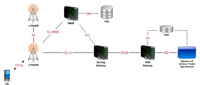
LTE System Architecture

LTE-System

eNodeB

EPS (Evolved Packet System) eNodeB covers the following functionalities:

  • Functions for Radio Resource Management
    • Radio Bearer Control
    • Radio Admission Control
    • Connection Mobility Control
    • Dynamic allocation of resources to UEs, both in the uplink and in downlink.
  • IP header compression and encryption of user data.
  • Selection of MME at UE attachment
  • Routing of user plane data towords Serving Gateway
  • Scheduling and transmission of paging messages
  • Scheduling and transmission of broadcast message
  • Measurements for mobility and scheduling

MME (Mobility Management Entity)

  • NAS signalling
  • NAS signalling security
  • Inter CN node signalling for mobility between 3GPP access networks (terminating S3)
  • UE Reachability in ECM-IDLE state (including control and execution of paging retransmission)
  • Tracking Area list management
  • PDN GW and Serving GW selection
  • MME selection for handovers with MME change
  • SGSN selection for handovers to 2G or 3G 3GPP access networks
  • Roaming (S6a towards home HSS)
  • Authentication
  • Authorization
  • Bearer management functions including dedicated bearer establishment
  • Lawful Interception of signalling traffic
  • Warning message transfer function (including selection of appropriate eNB)
  • UE Reachability procedures.

S-GW (Serving Gateway)

The Serving GW is the gateway which terminates the interface towards E-UTRAN.

For each UE associated with the EPS, at a given point of time, there is a single Serving GW.

The Serving Gateway covers the following functionalities:

  • the local Mobility Anchor point for inter-eNodeB handover;
  • sending of one or more “end marker” to the source eNodeB, source SGSN or source RNC immediately after switching the path during inter-eNodeB and inter-RAT handover, especially to assist the reordering function in eNodeB.
  • Mobility anchoring for inter-3GPP mobility (terminating S4 and relaying the traffic between 2G/3G system and PDN GW);
  • ECM-IDLE mode downlink packet buffering and initiation of network triggered service request procedure;
  • Lawful Interception;
  • Packet routing and forwarding;
  • Transport level packet marking in the uplink and the downlink, e.g. setting the DiffServ Code Point, based on the QCI of the associated EPS bearer;
  • Accounting for inter-operator charging. For GTP-based S5/S8, the Serving GW generates accounting data per UE and bearer;

NOTE: Connectivity to a GGSN is not supported.

PDN GW (PDN Gateway)

The PDN GW is the gateway which terminates the SGi interface towards the PDN.

If a UE is accessing multiple PDNs, there may be more than one PDN GW for that UE, however a mix of S5/S8 connectivity and Gn/Gp connectivity is not supported for that UE simultaneously.

PDN GW functions include for both the GTP-based and the PMIP-based S5/S8:

  • Per-user based packet filtering (by e.g. deep packet inspection);
  • Lawful Interception;
  • UE IP address allocation;
  • Transport level packet marking in the uplink and downlink, e.g. setting the DiffServ Code Point, based on the QCI of the associated EPS bearer;
  • Accounting for inter-operator charging;
  • UL and DL service level charging (e.g. based on SDFs defined by the PCRF, or based on deep packet inspection defined by local policy);
  • Interfacing OFCS through according to charging principles and through reference points
  • UL and DL service level gating control
  • UL and DL service level rate enforcement (e.g. by rate policing/shaping per SDF);
  • UL and DL rate enforcement based on APN-AMBR (e.g. by rate policing/shaping per aggregate of traffic of all SDFs of the same APN that are associated with Non-GBR QCIs);
  • DL rate enforcement based on the accumulated MBRs of the aggregate of SDFs with the same GBR QCI (e.g. by rate policing/shaping);
  • DHCPv4 (server and client) and DHCPv6 (client and server) functions;
  • The network does not support PPP bearer type in this version of the specification. Pre-Release 8 PPP functionality of a GGSN may be implemented in the PDN GW;
  • packet screening.


Wednesday, November 30, 2011

Wimax


WiMax, also known as IEEE 802.16, is a wireless digital communications system that is intended for wireless "metropolitan area networks". WiMax is designed to extend local WiFi networks across greater distances, such as on a university campus.

The WiFi/802.11 wireless local area, which is the network standard, is limited in most cases to only about 100 to 300 feet; however, Wimax can provide broadband wireless access for up to 30 miles for fixed stations and 3 to 10 miles for mobile stations. WiMax allows for more efficient bandwidth use, interference avoidance, and is intended to allow higher data rates over longer distances.

The IEEE 802.16 standard defines the technical features of the communications protocol. The WiMAX Forum offers a means of testing manufacturer's equipment for compatibility, as well as an industry group dedicated to fostering the development and commercialization of the technology.

In the next five years, Wimax will have an enormous impact on the cellular markets, particularly that of third-world countries, as well as that of the United States. The cost-effectiveness of WiMax to that of preexisting systems is much higher. One application that can be used by cellular companies is WiMax's ability to serve as a high bandwidth "backhaul" for internet or cellular phone traffic from remote areas back to an Internet backbone; WiMax may be an answer to reducing the cost of T1/E1 backhaul as well.

What will wimax services offer to the average consumer ?

WiMAX networks will provide broadband connectivity and mobile Internet anytime, anywhere, for any device and on any network with substantial increasing data speeds for applications to include online gaming, streaming video, video conferencing, VoIP and location based services.

In the U.S., Mobile WiMax services from Sprint and Clearwire will reach more than 150 million consumers by year end 2010. In rural areas, WiMAX technology will establish an affordable and efficient broadband network. The purchase and installation process of WiMAX technology is faster, simpler and cheaper than other offered solutions. Additionally, wimax can provide coverage despite the challenges of geography and the limited footprint of wireline-based solutions. In developing countries, WiMAX technology provides the opportunity to connect people with Internet and VOIP services faster and more affordably than wireline technology.

What is the speed of wimax for end users ?

Users can expect to have broadband access speeds ranging from 1-5 Mbps depending on the service provider offering. The data rate may also depend on a number of factors, including which frequency is being used, distance of the user from the base station or node, whether there is line of site or NLoS to the base station, and the number of users on the network. There is the potential to burst to higher speeds, but that would depend on the operator's plans and business model.

Key features of Wimax

  • Interoperability : A key differentiation for wimax is the interoperability of certified equipment, resulting in large economy of scale and assurance for service providers that equipment from different vendors is interoperable. 530 leading companies in the communications and computing industries, members of the Wimax Forum, are currently driving a common platform for the global deployment of IP-based broadband
  • Wider coverage : The technology behind wimax has been optimized to provide excellent coverage; wider areas, better predictability of coverage and lower cost as it means fewer base stations and backhaul, simple RF planning, shorter towers and faster CPE install times.
  • Lower cost : A standards based platform for wimax drives down costs and delivers volume economics to WiMAX equipment
  • Industry Standard : for all usage models (fixed to mobile). Wimax was designed to become the most cost-effective solution for carriers for any usage model from fixed to mobile. Newer versions of the WiMAX standard support higher speeds of mobility and always maintain backward compatibility with previous Mobile WiMAX releases.
  • Higher capacity : advantage of wimax is the use of Orthogonal Frequency-Division Multiplexing (OFDM) over CDMA which is used in older technologies like Edge, GPRS, and HSPA. OFDM delivers higher spectral efficiency and therefore higher data rate and overall system capacity.
How it works

In practical terms, WiMAX would operate similar to WiFi but at higher speeds, over greater distances and for a greater number of users. WiMAX could potentially erase the suburban and rural blackout areas that currently have no broadband Internet access because phone and cable companies have not yet run the necessary wires to those remote locations.

­ A WiMAX system consists of two parts:

  • A WiMAX tower, similar in concept to a cell-phone tower - A single WiMAX tower can provide coverage to a very large area -- as big as 3,000 square miles (~8,000 square km).
  • A WiMAX receiver - The receiver and antenna could be a small box or PCMCIA card, or they could be built into a laptop the way WiFi access is today.

A WiMAX tower station can connect directly to the Internet using a high-bandwidth, wired connection (for example, a T3 line). It can also connect to another WiMAX tower using a line-of-sight, microwave link. This connection to a second tower (often referred to as a backhaul), along with the ability of a single tower to cover up to 3,000 square miles, is what allows WiMAX to provide coverage to remote rural areas.

What this points out is that WiMAX actually can provide two forms of wireless service:

  • There is the non-line-of-sight, WiFi sort of service, where a small antenna on your computer connects to the tower. In this mode, WiMAX uses a lower frequency range -- 2 GHz to 11 GHz (similar to WiFi). Lower-wavelength transmissions are not as easily disrupted by physical obstructions -- they are better able to diffract, or bend, around obstacles.
  • There is line-of-sight service, where a fixed dish antenna points straight at the WiMAX tower from a rooftop or pole. The line-of-sight connection is stronger and more stable, so it's able to send a lot of data with fewer errors. Line-of-sight transmissions use higher frequencies, with ranges reaching a possible 66 GHz. At higher frequencies, there is less interference and lots more bandwidth.

WiFi-style access will be limited to a 4-to-6 mile radius (perhaps 25 square mile­s or 65 square km of coverage, which is similar in range to a cell-phone zone). Through the stronger line-of-sight antennas, the WiMAX transmitting station would send data to WiMAX-enabled computers or routers set up within the transmitter's 30-mile radius (2,800 square miles or 9,300 square km of coverage). This is what allows WiMAX to achieve its maximum range.

The final step in the area network scale is the global area network (GAN). The proposal for GAN is IEEE 802.20. A true GAN would work a lot like today's cell phone networks, with users able to travel across the country and still have access to the network the whole time. This network would have enough bandwidth to offer Internet access comparable to cable modem service, but it would be accessible to mobile, always-connected devices like laptops or next-generation cell phones.

Wifi Fundamentals


Conversions

1 MHz = 1,000,000 Hz
1 GHz = 1,000 MHz
1 GHz = 1,000,000,000 Hz

I.E.
- 2400 MHz is the same as 2.4 GHz
- 5800 MHz is the same as 5800 GHz

Hz = Radio Spectrum
Bits = data
M = 1,000,000
G = 1,000,000,000
There is a total of 83.3 MHz of Spectrum available in the 2.4 GHz Band

LICENSE FREE BANDS

ISM
ISM: Industrial, Scientific, and Medical
UNI-I (or UNII)
Unlicensed National Information Infrastructure
  • 902 to 928 MHz
  • 2,400 to 2,483.5 MHz
  • 5,725 to 5,850 MHz
  • 5,150 to 5,250 MHz
  • 5,250 to 5,350 MHz
  • 5,725 to 5,825 MHz

900 MHz Band

  • (902 to 928 MHz)
  • Data Rates are up to 3 Mbps ( Typical 2 Mbps throughput)
  • Non Line of Sight
  • Unaffected by weather
  • Only few Manufacturers for the products – proprietary technology
  • Expensive – Compared to IEEE 802.X technologies

2.4 GHz Band

  • Large bandwidth available (83.5 MHz)
  • High data rates possible (up to 11 Mbps)
  • With the 11g – 54 Mpps is possible
  • Equipment reasonably priced
  • Unaffected by weather
  • Line of Sight required for long range (greater the several hundred yards)
  • Used world-wide

5 GHz Band

  • 5.725 – 5.850 GHz Spread Spectrum Band
  • Virtually unlimited ERP on Point-to-Point links makes long range practical
  • Very high data rates possible
  • Equipment more expensive then 2.4 GHz equipment
  • Still greatly underutilized
  • High gain directional antennas focus signals
  • Ideal for point-to-point wireless backbone
Unlicensed National Information Infrastructure


Band 1
Band 2
Band 3
FREQUENCY
5.15 - 5.25 GHz
5.25 - 5.35 GHz
5.725 - 5.825 GHz
TX POWER
23 dBm EIRP
(200 mW)
30 dBm EIRP
(1 Watt)
36 dBm EIRP
(4 Watts)
APPLICATION
INDOOR USE ONLY
CAMPUS LINKS
LONG RANGE
(Several Miles)


RF FUNDAMENTALS

RF Communication

Full Duplex

  • Radio TX and RX data simultaneously
  • Requires a pair of Frequencies (one for TX and one for RX)
  • Fastest means of data transfer
Both radios are transmitting and receiving at the same time on different radio frequencies.


Half Duplex

  • Used by IEEE 802.11a,b,g and others
  • Time Division Duplex (TDD)
  • Bi-directional system
  • Only one radio transmits at a time
  • Radio buffers the data until it is its turns to transmit
  • Operates only on one radio channel
  • Typically less then half thru-put of the over-the-air data rate
Radios alternate transmit and receive on the same radio channel.


DEFINITIONS

dB
Difference (or ratio) between two signal levels. Generally used used to describe the effect of system devices on signal strength.
dBm
A signal strength level. 0 dBm is defined as 1 mW of power. Small signals are negative numbers. (e.g. - 83 dBm)
dBi
The gain of an antenna relative to an isotropic radiator. Used in calculating ERP and range.

NOTE: dB, dBm and dBi are used because systems’ powers, gains and losses can be calculated by simply adding and subtracting.
ERP
Effective Radiated Power, equal to the antenna gain added to the power into that antenna. (Technically, called EIRP.)
Gain and Loss

Amplification
Signal Loss


Remote Amplifier System


Effective Radiated Power (ERP)

dBm vs. Watts

dBm
0
1
2
3
6
10
15
20
30
33
36
40
50
60
Power
1.0 mW
1.3 mW
1.6 mW
2.0 mW
4.0 mW
10.0 mW
32.0 mW
100 mW
1 Watt
2 Watts
4 Watts
10 Watts
100 Watts
1.000 Watts
dBm = 10 log

dBm = 10 log

dBm = 10 log

Example: Convert 250 mW to dBm
10 log

250

= 10 x 2.39 = 24dBm

1 mW

Rule Of Thumb
Double/Half Power:
Add/Subtract 3dB
Ten Times/One-tenth Power:
Add/Subtract 10dB
Spread Spectrum Technologies

Frequency Hopping (FHSS)
  • The radio carrier hops around the band.

Direct Sequence (DSSS)

  • The radio carrier signal is “spread out” on a specific channel

Channels For FHSS

Each data packet sent on one of 82 channels.
  • Next packet randomly hops to another channel.
  • Signal itself not “spread” - occupies narrow bandwidth.
  • Signals “hop” around interfering signals.
Channels For DSSS System

802.11 Radio Channels
All Radios in One Network Operate on a Single Channel

DSSS Spectrum - IEEE 802.11b

Direct Sequence Spread Spectrum (DSSS)
Frequency Channel in 2.4 GHz (IEEE 802.11)


Overlapping Channels

802.11 Radio Channels Overlap

802.1 Protocol Summary

Standard
Modulation
Air Data Rate
Frequency Band
802.11
FHSS
DSSS
2 Mbps
2.4 GHz
802.11a
OFDM
54 Mbps
UNII
802.11b
DSSS
11 Mbps
2.4 GHz
802.11g
OFDM
DSSS
54 Mbps
11 Mbps
2.4 GHz
802.1x
N/A
Authentication and
Access Control
All